CALL US 888-825-4716
Understanding Technical Data for Stormwater Management Solutions
Engineering Specifications for StormChamber Systems
Each chamber will be formed from high molecular weight/high density polyethylene.
Each chamber will be composed of at least 40% recycled material.
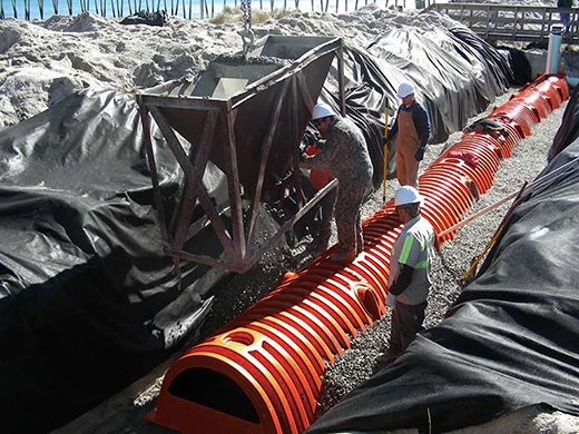
The stone base that the chambers are placed on will not be compacted in order to avoid compaction of the stone-soil interface, which restricts soil infiltration.

The chamber system will be designed without filter fabric under the chambers in order to avoid restriction of soil infiltration, which occurs from the normal clogging of the filter fabric from sediment and debris deposition.
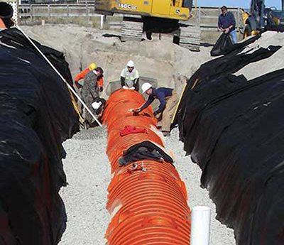
Use of filter fabric between the soil and stone backfill layer and lining the side walls of the excavated area will be required to prevent intrusion of soil or silt into the chambers and surrounding stone.
Each chamber will be capable of exceeding 32,000 pounds per square foot (i.e., four times the AASHTO H-20 Wheel Load Rating).
Each chamber will be capable of being installed with a minimum of 25 feet of cover above the crown of the chamber.
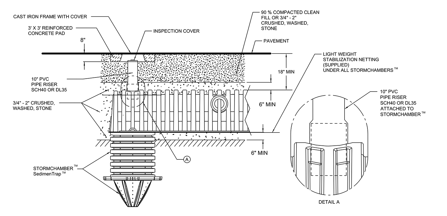
Each chamber system will be capable of being installed with a minimum of six inches of stone base.
Each chamber will be 34.04″ high, 60″ wide and 102.5″ long.
Lay-up length will be 8′-1″ (start and end unit) and 7′- 7″ (middle unit).
Each chamber will have 14 ribs of approximately 3.6″ in height, 3.8″ wide at the top and tapering to 4.4″ at the bottom. Spacing of the ribs at the bottom of the chamber will be approximately 4.9″ and approximately 3.2″ at the top. One smaller rib sized dimensionally to effectively nest under and interlock to connect units will be 2.9″ high, 3.3″ wide at the top of the rib, and 4.1″ wide at the base.
Overall height to the inside rib will be 30.44″.
Overall height to the outside rib will be 34.04″.


Each chamber will have a defined top portal which is structurally enhanced to compensate for loss of structural integrity when apertures are cut open to receive pipe. Each such portal will be capable to receive up to a 12″ PVC pipe.
Each chamber will have defined side portals on opposing sides which are structurally enhanced to compensate for loss of structural integrity when apertures are cut open to receive pipe.
Invert height for a 10″ PVC pipe through a defined side portal will be 17.49″.
Invert height for an 8″ PVC pipe through a defined side portal will be 18.49″.
Each chamber will be capable to accept an 8″ or 10″ PVC feed pipe through a defined side portal.
Each chamber will be capable to accept up to a 30″ OD pipe through its end wall.
Each chamber will be capable of storing a minimum of 14.53 cubic feet per lineal foot with 6″ or stone above and below the chamber.
Each chamber system will be designed without utilizing a header pipe manifold system.
Stone diameter will be 3/4″-2″.


